Magnet Tolerance & Geometry Limitations.
Magnet Tolerance & Geometry Limitations.
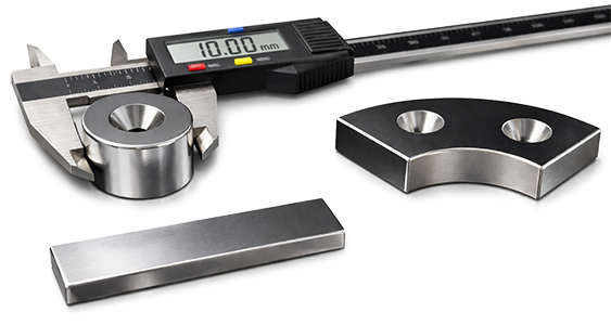
The purpose of this article is to outline the practical tolerance and geometry limitations you can expect when specifying permanent magnets, with a focus on how material type and manufacturing methods constrain what’s feasible and cost-effective.
Because magnets (especially sintered neodymium) are not machined like typical metal parts, achieving tight tolerances, thin sections, sharp internal corners, or fragile features can increase breakage risk, lead time, and cost.
Use the guidelines below as a starting point to set realistic drawing tolerances, and reach out if you need help balancing performance, durability, and manufacturability for your specific application.
Note: Some of the magnet tolerance limitations listed below are general guidelines and can be stretched in special circumstances. If you have any questions about a limitation, please do not hesitate to contact us.
Sintered Neodymium Magnets.
Sintered neodymium magnets are produced by pressing magnetic powder into shape and then sintering it at high temperature. The resulting material is magnetically strong, but it’s brittle and more difficult to machine to tight tolerances. Designs that are especially prone to chipping or cracking during processing often cost more due to higher scrap and handling risk.
Tolerance Limitations
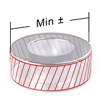
Keep the tolerances as loose as your design will permit. Looser design tolerances = lower production cost.
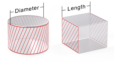
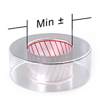
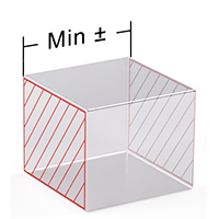
| Magnet Size Range (Dia or Length) | Min Outer Dia Tolerance | Min Inner Dia Tolerance | Min Length Tolerance | Min Angle Tolerance |
|---|---|---|---|---|
 |
 |
 |
 |
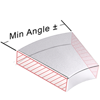 |
| Less than 5mm | ±0.08mm | ±0.08mm | ±0.08mm | ±1.0° |
| Less than 50mm | ±0.1mm | ±0.1mm | ±0.1mm | ±1.0° |
| Less than 100mm | ±0.15mm | ±0.15mm | ±0.15mm | ±1.0° |
| Greater than 100mm | ±0.2mm | ±0.2mm | ±0.2mm | ±2° |
Size Limitations
Maximum Magnet Size Limitations
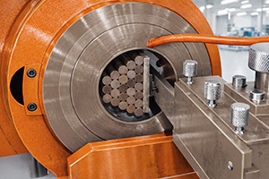
 The Maximum Neodymium magnet size is limited by what can be reasonably magnetized after machining. During the magnetization process the magnet, or stack of magnets are placed into a magnetizing coil that generates a magnetic field strong enough to magnetize the material inside the coil. The size of the magnetizing coils “inside bore diameter” is the main limiting factor for maximum size in most cases.
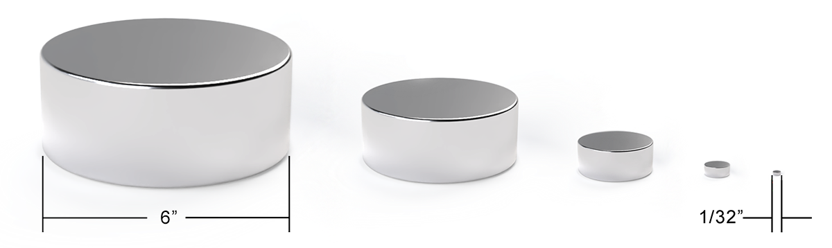
Minimum Magnet Size Limitations
 Minimum magnets sizes are limited by brittleness and machining capabilities.
If a magnet cannot fit inside of the magnetizing coil, it likely cannot be magnetized in one piece.
| Standard Magnetizing Coil Dimensions | Coil Magnetization Direction |
|---|---|
| Coil Bore (Inside Dia): 6″ (152.4mm) Coil Height (Bore Depth): x 4″ (101.6) 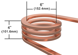 |
The magnetization direction is axially aligned with the coil diameter as shown below.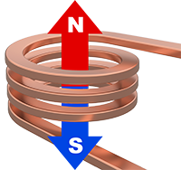 |
Coil Volume & Magnetization Direction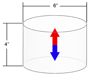 |
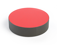
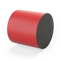
Axially Magnetized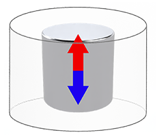 |
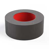
Diametrically Magnetized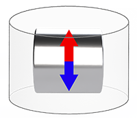 |
Magnetizing in Multiple Pieces
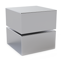
In some cases, if a magnet is too large to be magnetized in a single piece, the magnet can be made in multiple pieces and magnetized separately then assembled together later.
2 Magnet halves assembled together will behave as a single magnetic whole. With a very slight flux loss due to the gap between them created by the surface roughness, plating, and adhesive.
Whether or not a magnet can be assembled after magnetization depends largely on the magnetization orientation.
- When 2 large pieces of the magnet are naturally repelling assembling them with glue is not feasible, they will need an external housing to force the pieces together.
- In cases where the 2 pieces are naturally attracting, a small amount of glue between them is often enough to ensure a strong bond and good performance.
Other Geometry Limitations
Minimum Thru-Hole Size
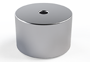 Typically 1/32” or 1mm minimum. However, the minimum thru-hole size is limited by the depth of the hole. Drilling long thin holes through a permanent magnet can be difficult and cause tool breakage. A general rule is to keep the Hole ID no less than four times the depth.
For example, a 20mm deep thru-hole should have an ID no less than 5mm”
Brittle Shapes
Neodymium is brittle (similar to ceramic), and brittle shapes can be difficult to machine successfully without cracking or breaking during production (and sometimes even later during assembly or use).
- Sharp edges, thin wafers, and narrow cross-sections are the usual failure points.
- They tend to chip during grinding/handling, or more commonly break later when the magnet experiences a sharp impact.
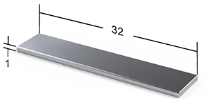
Brittleness Ratio Limit: 32:1
As a rule of thumb, try to keep your longest dimension to thinnest dimension under 32:1. A magnet outside this ratio can be very difficult to machine without breaking during production, and it will also be more fragile in real-world use. Long, skinny magnets are especially prone to cracking from normal handling and packaging, and they often need extra process steps (slower grinding, more rejects, custom fixturing) that raise cost and lead time.
Need Assistance Optimizing Magnet Geometry?
If you need help optimizing your magnet for performance and cost, see our article on magnet design optimization or contact us to talk to a friendly engineer.
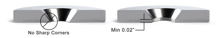
Countersink Holes
For countersunk holes, the taper often runs right into the thru-hole diameter, which creates a sharp “knife-edge” corner (a very thin ring of magnet material). In a brittle material like NdFeB, that thin ring is a classic failure point. It’s where you’ll see:
- Chipping during machining (especially during final grind or deburr/tumble)
- Plating damage caused by chipped corners that later turn into peeling of the plating and rust.
- Cracks during assembly if the screw doesn’t seat perfectly, the countersink angle is mismatched, or the screw is tightened a little too hard
- Breakage in use from vibration, impacts, or bending loads transferred through the screw head into that thin rim
Recommended design fix: add a flat spot (a small land) at the corner.
Instead of letting the countersink taper intersect the thru hole as a sharp point, create a short flat before the thru hole. This does a few good things:
- Reduces stress concentration by eliminating the knife-edge geometry
- Improves plating durability because plating is less likely to thin out and crack at a sharp corner
- Makes assembly more forgiving if the screw angle or seating isn’t perfect
Threaded Magnets
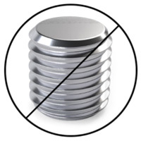 |
Not Possible To Thread The Magnet Itself It is not possible to machine reliable threads directly into sintered permanent magnet material (like NdFeB). The material is hard and very brittle, so internal threads (tapped holes) will chip, crack, or crumble during machining or when a fastener is tightened. Even if you manage to cut “threads,” the magnet has very low toughness and poor thread shear strength, so the first real assembly torque or vibration event can strip the feature or fracture the part. |
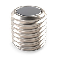 |
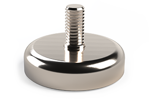
Threaded magnets are made by adding threads to something other than the magnet: The most common solution is a steel cup/housing that:
|
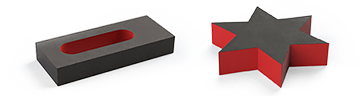
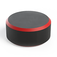
| Male Threaded Cup Magnets The magnet is embedded into a steel cup. The stud is bonded to the cup for mounting with a nut. |
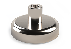
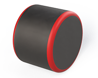
Female Threaded Post The magnet is embedded into a steel cup. A threaded post is attached to the top of the cup and accepts a screw. |
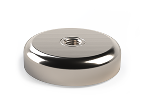
Female Threaded Cup Magnets A magnet with a thru hole is embedded into a steel cup. A threaded post bonded to the steel cup runs through the magnet hole. |
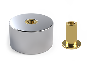
Threaded Inserts A threaded insert runs through a counterbore thru-hole in the magnet. This keeps the mounting hardware flush with the surface of the magnet. |
 |
 |
 |
 |
Common Machining Methods.
Because neodymium (NdFeB) is a high-value material, most manufacturing methods are designed to waste as little material as possible. Production typically starts by pressing magnet powder into a compact and sintering it into dense blocks.
From there, manufacturers use diamond slicing to turn large blocks into blanks, then rely on grinding-based processes (surface, double-disc, centerless, and ID grinding) to bring parts to final size with minimal scrap. Features like holes and countersinks are created with diamond drilling or coring, and edges are often chamfered or tumbled to reduce chipping during handling.
Finally, magnets are cleaned and coated (commonly nickel, epoxy, or other protective finishes) to improve corrosion resistance before inspection, magnetization, and packaging.
The specific manufacturing method depends largely on the desired end shape, tolerance requirements, and the risk of breakage for brittle geometries. Below are a few examples of machining methods commonly used for shaping Neodymium magnets.
 |
Diamond cutting/slicing (turning big sintered blocks into blanks)Thin diamond blades slice large sintered NdFeB blocks into smaller “blanks” (slabs/bricks) that are then machined to final shapes. This is usually the first “real” shaping step after sintering because it’s fast, relatively low waste, and scalable. Slicing also helps manufacturers maximize yield by nesting blank sizes efficiently within the original block. Note: slicing is not a finishing process. Cut faces can have minor chipping and saw marks, and the thickness can vary slightly across the part. Most sliced faces still need grinding if you care about flatness, parallelism, or tight dimensional control. 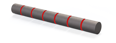 |
 |
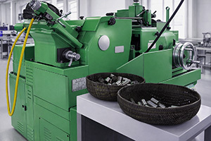
Surface grinding (making faces flat and to size)Surface grinding removes small, controlled amounts of material to make faces flat, parallel, and on-dimension. This is one of the most common finishing processes for block magnets and “brick” blanks because it provides good dimensional control without introducing large cutting forces. It’s often used to control length/width/height.
 |
 |
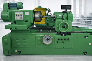
Centerless grinding (round magnets at scale)Cylindrical magnets are ground without centers, supported between a grinding wheel and a regulating wheel. This is ideal for producing consistent diameters in volume because it’s fast, repeatable, and doesn’t require holding the part in a chuck (which can crack brittle parts). Centerless grinding is commonly used for disc magnets, rods, and pins, and it’s one of the best options when diameter consistency matters.
 |
 |
Diamond coring/drilling (thru-holes, cores, countersinks)Thru-holes in sintered neodymium are typically made by abrasively grinding with a diamond-bonded hollow core drill, not cutting like a twist drill. The tool removes material as grit, which reduces the chance of catching and cracking the magnet. This method is used for thru-holes, cores, and sometimes the first stage of a countersink feature.
 |
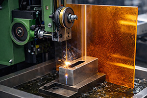 |
Wire EDM (complex profiles)Wire EDM uses a thin wire to cut intricate outlines in conductive materials. For magnets, it’s typically used on pre-cut blocks or magnet stacks when unusual profiles are needed that can’t be achieved efficiently with grinding alone. It’s a useful option for special shapes, internal corners, keyways, and complex 2D profiles. Note: EDM is usually not the cheapest path. It’s often chosen when the geometry forces it, or when you’re making a specialty part in lower volume. Final grinding and sharp corner breaking considerations still apply.
 |
 |
Chamfer (reduce chipping)Chamfers are small bevels ground onto edges to remove sharp corners. This reduces edge chipping, makes parts safer to handle, and improves durability during packaging and assembly. Chamfers also help protect coatings, since sharp edges are where plating is most likely to thin out, crack, or flake. Note: chamfers are more common on larger magnets where a controlled bevel is needed. On small magnets, tumbling is usually the more economical edge-conditioning step.
 |
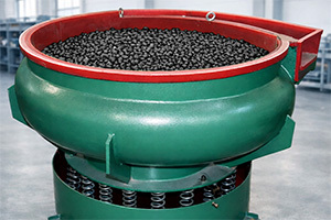 |
Tumbling (brakes corners to reduce chipping)Parts are gently tumbled with media to break sharp edges and corners. Tumbling is a cost-effective way to reduce handling damage by rounding sharp corners. Design note: tumbling is not very precise. It produces a “softened” edge rather than a controlled diameter, and results can vary based on media type, time, load size, and part geometry. Rounded corners less than 1mm radius are not called out in the manufacturing drawing as a specific radius, instead it is defined as “breaking the edge” to a minimum radius.
 |