Overmolding Magnets in Plastic
This article provides a practical overview of techniques for embedding magnets into injection-molded plastics and elastomers, with a focus on overmolding and insert molding methods. This guide will cover the key design considerations and limitations involved in molding magnets directly into plastic components.
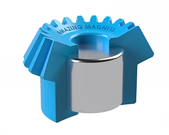
Overmolding or embedding magnets into plastic (also known as co-molding or insert-molding magnets) involves placing a magnet into a mold and injecting molten plastic around it. This method securely captures the magnet within the plastic housing, creating a durable, mechanically bonded assembly.
⚠️ Disclaimer
The information provided in this article is for general informational purposes only and is not a substitute for professional advice. Always consult with a qualified engineer for project-specific guidance.
Need a Quote?
Amazing Magnets LLC Designs, Develops, and Produces overmolded magnets and assemblies. Need help in plastic design or magnet optimization? Contact us to speak with a friendly engineer.
Contact UsCases for Molding Magnets in Plastic
 |
Improved Safety and Durability Loose or dislodged magnets can harm people, pets, and appliances. Plastic-embedded magnets have a much higher resistance to becoming detached and dislodged in dynamic environments. |
 |
Hermetic Sealing Full encapsulation of the magnet with a hermetic seal can shield magnets from corrosion in harsh environments. Medical-grade or food-grade plastics can be used to protect sensitive environments from the magnet. Dielectric plastics can be used to electrically isolate the magnet for electronic or sensor assemblies. |
 |
Why to avoid glues and tapes: Gluing and taping magnets to plastic can lead to long-term reliability issues. Proper surface preparation and bond success are difficult to verify as failures may not appear immediately and can emerge after the product reaches the customer. The surface preparation and application process are prone to human error. "All it takes is one person on the assembly line not paying attention to cause a large error rate." |
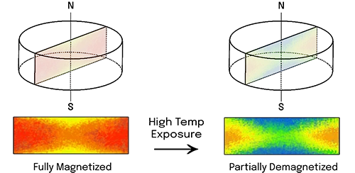
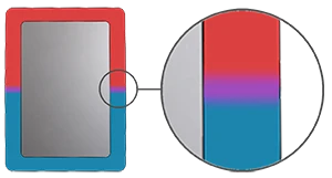
Injection Mold Heat Demagnetization
The heat of injection molding will partially demagnetize most magnets. There are ways around this, such as choosing a high-temperature magnet grade, but those can be much more expensive. In most cases, the magnet can be magnetized after molding (post-mold magnetization). This can be done by placing the entire molded assembly, plastic housing and all, inside a large magnetization coil to be magnetized.
A benefit of molding an unmagnetized magnet is that it will behave like a simple piece of metal with no noticeable magnetic properties. This makes it much easier to handle during assembly into the mold tool and demolding.
 |
 |
- Curie Temperature: If a magnet is heated close to or beyond its Curie temperature, it loses its ability to retain a magnetic field. Even if you try to remagnetize it later, it won't perform the same. The magnet is essentially ruined.
- Max Operating Temperature: If a magnet is heated close to or beyond its maximum operating temperature, it will lose some strength. However, it can usually be remagnetized to recover most of its strength. Remagnetization involves placing the magnet, or the entire device, inside a magnetizing coil.
- Important Note: These temperatures are general guidelines for comparing materials. The actual limit depends on the magnet grade, geometry, and magnetic circuit conditions (e.g., how the field interacts with other magnets or ferrous metal components).
If you have questions about your magnets' performance at elevated temperatures, please don't hesitate to contact us.
To see a full list of magnet materials, see our materials and grades chart.
| Material | Curie Temperature (Tc) Getting close to or surpassing this can cause permanent magnet damage. |
Max Operating Temperature Getting close to or surpassing this can cause strength loss that can only be reversed by remagnetizing the magnet. |
Strength Range BHmax (MGOe) |
|---|---|---|---|
| Sintered NdFeB | 310°C (590°F) | 80–230°C (176–446°F) | 33–56 |
| Bonded NdFeB | 360°C (680°F) | 80–150°C (176–302°F) | 3–12 |
| SmCo (Grades 1-5) | 727°C (1340.6°F) | 250°C (482°F) | 16–30 |
| SmCo (Grades 2-17) | 825°C (1517°F) | 300°C (572°F) | 16–24 |
| AlNiCo | 890°C (1634°F) | 450–550°C (842–1022°F) | 22–30 |
| Ceramic | 460°C (860°F) | 250°C (482°F) | 0.8–4.4 |
Post-Mold Magnetization Options
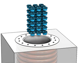
Standard Coil Magnetization
The simplest and most common form of post-mold magnetization involves placing the entire magnet and plastic housing assembly into a magnetizing coil. Plastic does not interfere with the magnetic field, so the magnet can be fully charged within the housing. Often, multiple parts can fit into the coil at once, allowing for batch magnetization. To learn more about how the magnetization process works, check out our article: How Neodymium Magnets are Made
 |
Standard Magnetizing Coil Dimensions Coil Bore (Inside Diameter): 6″ (152.4mm) Coil Height (Usable Bore Depth): 4″ (101.6mm) Note: These dimensions are common but not standardized. Different Magnet Manufacturers will have different capabilities. Cycle Time Capacitor charge: <30 seconds Magnetization Time: 2–10 milliseconds Assembly time (Placing Parts into the Coil): <60 seconds. Varies by batch size and part orientation/assembly time. |
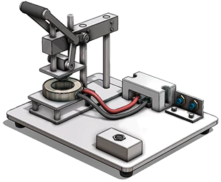
Custom Magnetization Tooling
In some cases, standard coil magnetization isn't feasible. This may be due to the plastic housing being too large to fit into the coil, or because the assembly includes multiple magnets with alternating polarity which would all become aligned in the same direction if magnetized in a standard coil.
In these scenarios, custom magnetization tooling can be created to magnetize the embedded magnets after molding. This magnetization process can be automated via robotic armatures for high volume applications.
 |
Additional Costs: Custom magnetization tooling requires a one-time setup cost, typically around $1,000 or more depending on the complexity of the tool. This covers specialized engineering and fabrication of the custom magnetizer. Because each part must be magnetized individually, there is also a small per-piece labor fee to cover the extra operator time during the magnetization process. Important Design Note: Not all magnet assemblies can be post mold magnetized, even with custom magnetization tooling. This is typically due to size constraint conflicts between the part geometry and the magnetization tooling size requirements. If you're unsure whether your design qualifies for post mold magnetization, we'd love to hear from you—this is exactly the kind of problem we specialize in. |
Insert-Molding vs. 2-Shot Molding
There are two primary methods for capturing the magnet inside the plastic housing during the molding process: “Insert-Molding” and “Overmolding or 2-Shot Molding”. Design Note: For both insert molding and 2-shot molding the tooling must open wide enough for an operator or automated system to insert the magnets; this fact adds some extra cost to the tooling. For alternatives to overmolding and insert molding magnets see the below articles on Alternatives to Molding.
Insert Molding
The magnet is placed into a fixed cavity or “seat” in the mold before plastic injection. The molten plastic then flows through the mold and around the magnet capturing it in place. The molded magnet is then “Post-Mold Magnetized”.
Insert Molding typically leaves one or more faces of the magnet exposed (showing) in the final part. Insert-molding is common for low- to mid-cost parts where full enclosure (hermetic sealing) of the magnet isn't critical.
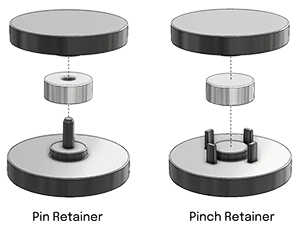 |
Magnet Retaining Features in the Mold The magnet must be securely restrained within the mold in all directions. If unrestrained, the magnet could shift or float out of position during injection. Pin Retainer: A through-hole in the magnet aligns with a pin in the mold, preventing lateral movement. Pinch Retainer: The magnet is held in place by side pins or arms. |
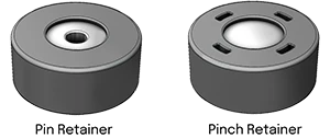 |
Magnet Retaining Feature Marks on the Part A defining feature of insert-molding is that the tool directly contacts the magnet to hold it in place during the plastic injection cycle. There will be pin marks or partially exposed areas on the final part where the magnet is showing through the plastic. |
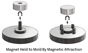 |
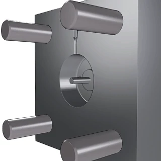
Molding Live Magnets In some cases, using a pre-magnetized magnet can help hold the magnet in place acting as one of the restraining axes. This only works if the magnet can withstand plastic flow from dislodging it. Re-magnetization is often required afterward to undo any heat demagnetization that occurs. This process is limited by the magnet size and mold complexity. A live magnet will be attracted to and magnetize the mold tool which can cause problems with assembly and mold tool function. |
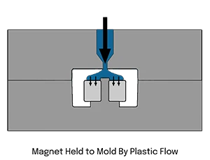 |
Using Plastic Flow Direction to Keep Magnet in Place If the plastic flow direction and injection pressure allow, an unmagnetized magnet can be placed in the mold unrestrained along one axis, allowing the flowing plastic to push it into position and hold it securely during molding. This approach minimizes pin marks and reduces the number of exposed magnet surfaces on the finished part. |
Overmolding (2-Shot Molding)
Overmolding is a method of embedding magnets into plastic by fully encapsulating them with no exposed areas. The part is molded in two stages: after the first shot forms the shell, the magnet is placed inside the shell, and a second layer of plastic is molded over it to seal it completely. This technique provides complete encapsulation and hermetic sealing, making it ideal for protecting magnets in harsh environments or sensitive applications—such as medical devices used inside the body.

 |
Bonding the First and Second Shot The two plastic injections must bond together to create a durable hermetic seal. Because the plastic cools between the first and second shot, the material options for overmolding magnets are limited to those that will bond together again after the first shot has cooled. Not all materials are capable of bonding after the first shot has cooled. This process often involves post-mold magnetization. |
Magnet Retaining Features
Simple retaining features can be machined directly into the magnet to improve retention when embedding magnets into plastic. These features help lock the magnet in place once the plastic cures around it. While this adds a small additional cost—typically just a few cents per magnet—it can be a significant percentage of the total cost for small magnets.
For more details on shape and size constraints, see our article: Magnet Geometry Limitations
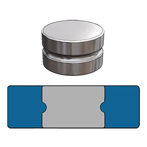 |
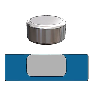
Groove Magnet The groove method is a good way to hold the magnet in place without greatly affecting the magnet's strength. Holding the magnet in the center like this allows the magnet to be flush with the plastic surface on both sides. A groove feature can be created on cylinder or block shape magnets. Design Note: The groove should be designed deep enough to hold the magnet firmly within the plastic housing, considering the forces that will be acting on the magnet and the plastic's flex during use (bending, twisting, etc). Size Limitations for Groove Magnets: Minimum Magnet Size: 2mm x 2mm. Minimum Groove Inside Radius R0.5mm. |
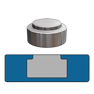 |
Step Magnet The step shape can be a very secure method to retain a magnet. The step can be created on both sides of the magnet if needed. This can be done on both cylinder and block shaped magnets. Design Note: The step feature will reduce some of the magnet's attraction strength at the stepped surface. Alternative to insert-molding: Instead of insert-molding, a step magnet can sometimes be inserted into a plastic part from behind. If the molded part contains a complementary step feature to retain the magnet in the forward direction, and all the force acting on the magnet is towards the step, the magnet can be retained from backing out of the hole via a snap-fit or other secondary retaining feature. Size Limitations: Minimum Magnet Size: 2mm x 2mm. Minimum Step Depth: 0.5mm. Minimum Step Width: 0.5mm. |
 |
Rounded Magnet The rounded method is a low-cost alternative to the step method, as the corners are rounded via tumbling. Almost all neodymium magnets are tumbled before plating to protect the edges from chipping and damage. This extra rounded feature is created by extending the time duration of the tumbling to create a larger radius. Design Note: Caution should be used when implementing this retaining method, as it is prone to failure if done incorrectly. If the plastic housing is not rigid enough the rounded magnet can rock or squeeze out of place. Also, tumbling can cause corner deformation on plate and block shaped magnets. Size Limitations: Minimum Magnet Size: 2mm x 2mm. Corner Radius: 0.25mm–2mm (depending on magnet geometry). |
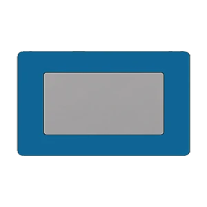 |
Full Plastic Encapsulation Industries like medical, marine, and food processing often require full plastic encapsulation to ensure superior corrosion resistance and meet regulatory material standards. Design Note: Full encapsulation is typically achieved through two-shot molding, or compression molding for PTFE (Teflon) housings. Size Limitations: The minimum plastic wall thickness to form a durable hermetic seal is 1mm. However, this varies by magnet geometry and use case. The thinner the plastic the weaker the hermetic seal between the 2 plastic halves as there is less surface area for the 2 plastic halves to bond. |
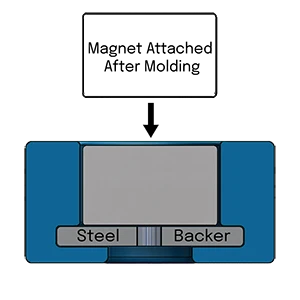 |
Insert Molded Steel Backer Instead of overmolding the magnet directly, you can overmold a steel backer and attach the magnet to the backer after molding. This method eliminates the need for post-mold magnetization. Design Note: For the magnet to stay in place, the steel backer must be designed to be more attractive to the magnet than whatever the magnet will be interacting with. A common technique to ensure the magnet prefers the backer side is to introduce a small gap between the magnet and the plastic surface, while keeping the magnet in direct contact with the steel backer. This small gap can also protect the magnet from direct impact damage. |
Embedding Magnets Into Flexible Materials Like Silicone
Magnets can be molded into Thermoset elastomers like silicone (LSR) or HNBR, as well as Thermoplastic Elastomers like Santoprene or TPU. The ideal material depends on your application. The most common materials chosen for overmolding magnets are liquid silicone rubber (LSR) and Thermoset Polyurethane (TPU).
Note: Embedding magnets securely into a flexible material can be challenging. If the material is flexible enough, a magnet can easily slip out through a pin hole left by insert-molding or tear a thin layer of the material. This issue is primarily seen in low-durometer silicones (around 20–70 Shore A). Harder grades don't typically exhibit this problem.
Solution A: Complete Encapsulation (Overmold)
Because the magnet can slip out of a pin hole left over from insert-molding, we recommend complete encapsulation of the magnet via two-shot overmolding. This way there will be no pin holes available for the magnet to escape.
Solution B: Pinned Steel Backer (Insert-Mold)
In this solution a stamped steel backer with some holes on the outer edge is insert-molded. The holes in the steel backer allow the plastic to flow around and through the holes effectively pinning the steel backer in place. The magnet will then be held in place by the steel backer.
Solution C: Silane-Based Adhesion Promoter (Supplementary)
In some cases, magnets can be treated with a silane-based adhesion promoter before molding. This primer chemically modifies the surface of the magnet, typically through a thin coating that introduces reactive silane groups. During the molding process, these groups bond covalently with the silicone matrix as it cures, forming a much stronger and more durable bond than simple mechanical retention alone.
This solution can be used as an additional retaining mechanism along with Solution A or B.
This additional security measure is highly recommended for safety-critical applications, including children's toys, where a magnet becoming dislodged from the silicone part could be a health hazard.
Additional Injection Molding Tips
For more details on general injection molding techniques and considerations, you can find helpful design guides and examples from companies like Protolabs – Injection Molding Design Tips.
Alternatives to Overmolding
While overmolding is one of the most secure and permanent ways of embedding magnets into plastic, it may not always be feasible due to magnet configuration, size, or tooling constraints, or material compatibility. Fortunately, there are several alternative attachment methods—each with its own advantages and ideal use cases.
Have Questions? We're Here to Help.
Speak with a friendly Amazing Magnets engineer about your overmolding project.
Contact Us